BMA360, Part 6: Samples Off DSP4, and an Index Four Times Too Big
Published:
Part 5 got my code running inside DSP4’s interrupt. Next came the first microphone audio out of the chip, a register readout that disagrees with it, and an addressing bug that produced confident wrong numbers.
The receive ring
DSP4 receives on serial port 0 (SPORT0) in 24-bit words. Each time the interrupt runs, DMA has filled one buffer of 8 frames, and the vendor code keeps three of those buffers in a ring. One pointer in data memory, 0x256dc4, always holds the address of one of the three.
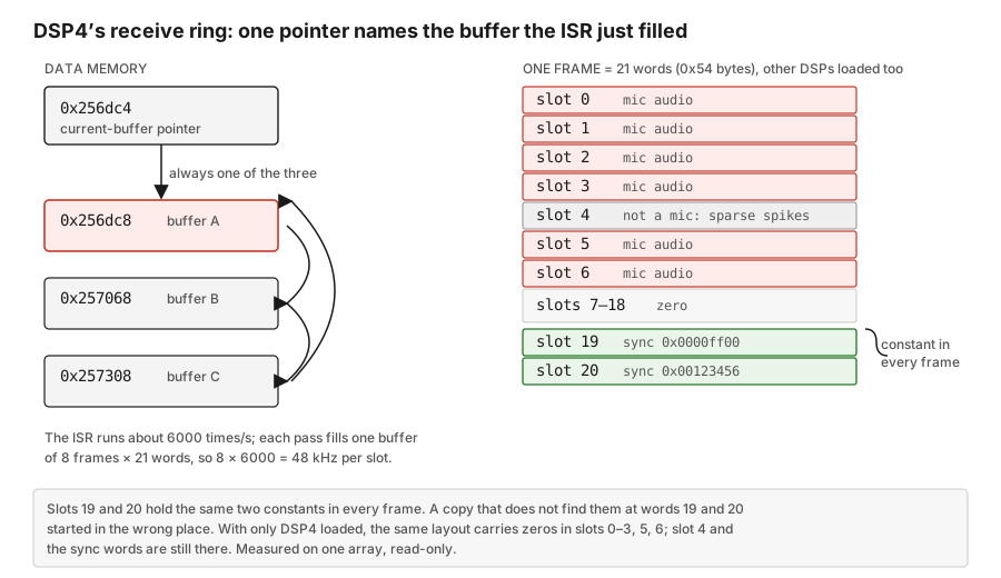
The interrupt runs at 5999.6 per second on the stock image; 8 frames per pass makes 48 kHz. Slots 19 and 20 hold the same two constants, 0x0000ff00 and 0x00123456, in every frame. A copy that does not find them at words 19 and 20 started in the wrong place, so every read I take checks them first.
A frame of real audio
With DSP4 loaded alongside other DSPs, loaded one at a time, my hook reads the pointer and copies the buffer it names. This is one such copy, from the fourth hook session on array B:
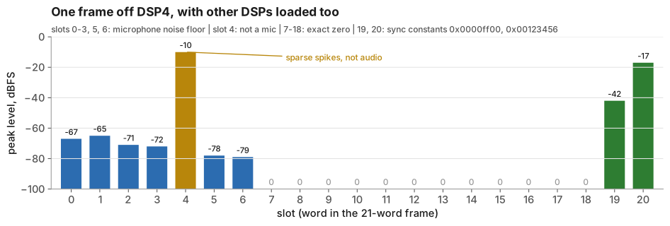
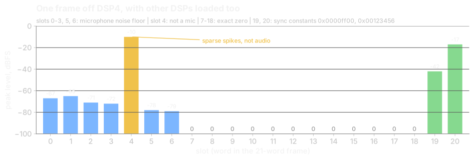
Six slots carry a microphone noise floor. Across those sessions it sat between -61 and -85 dBFS and moved around the way a live acoustic floor does. Slot 4 is something else: sparse spikes up to -10 dBFS. The sync words were in place in 24 of 24 frames.
In the same pass the hook summed those six slots into a broadside beam and compared it with the same sum computed from the snapshot. The two match bit for bit. That shows my code copies the right block and does the arithmetic right. It says nothing about direction or beam quality: six slots, no delays, one snapshot.
What is actually in the slots
With only DSP4 loaded, the same buffer looks different. Here are 128 frames, 16 dumps of 8 frames each, read straight over SPI:
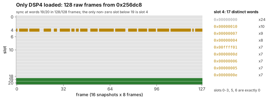
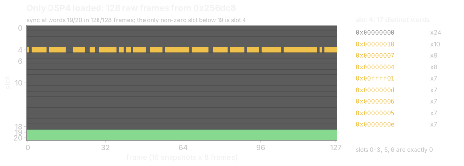
No microphone audio at all, just slot 4 counting through small values and the sync words. So I wrote a hook that copies SPORT0’s own registers into data memory, because SPI can read data memory but not the 0x31xxxxxx register space:
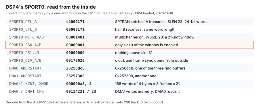
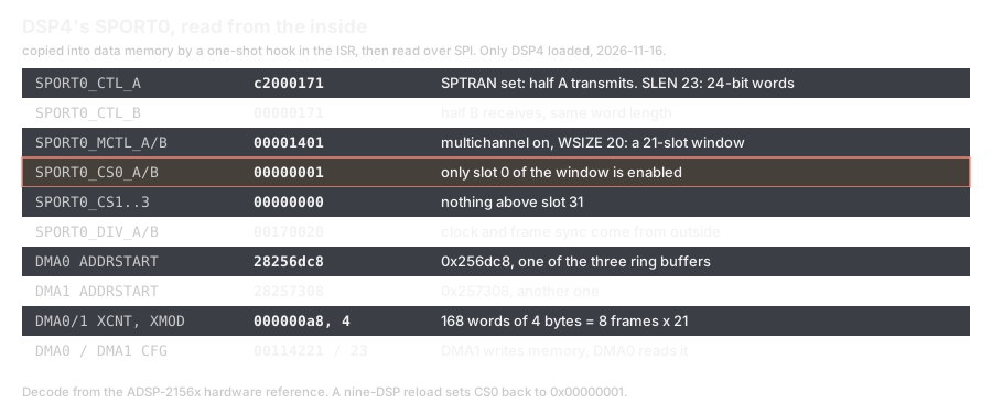
The DMA geometry matches the ring exactly: 168 words of 4 bytes, 8 frames of 21. The surprise is the channel select. CS0 = 0x00000001 enables only slot 0 of the 21-slot window, on both halves. By the hardware reference the SPORT should write slot 0 and nothing else, so the sync words and slot 4 are probably written by the firmware, and with only DSP4 loaded slot 0 itself is zero.
That leaves an open question I have not closed. With other DSPs loaded alongside DSP4, slots 1 to 3, 5 and 6 carry a noise floor that looks exactly like microphones, and a nine-DSP reload sets CS0 back to 1. On array A, setting CS0 to 0x001fffff with the stock FPGA image still showed mic data in slots 0 to 6. Where the words in slots 1 to 6 come from with only slot 0 enabled, I do not know yet. My own DSP image will set CS0 to 0x1fffff explicitly and not depend on the answer.
Words, not bytes
To make the copy loop cheaper I wanted it to load through an index register, DM(disp, I4), instead of 48 absolute addresses. The first probe installed, ran one armed pass, and reported zero misses. Then I compared the indexed copy against an absolute copy taken in the same pass, word for word.
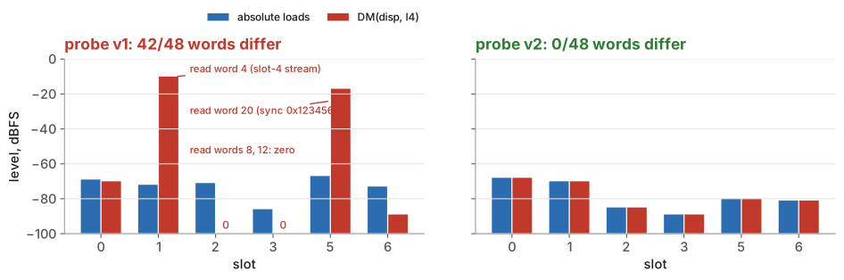
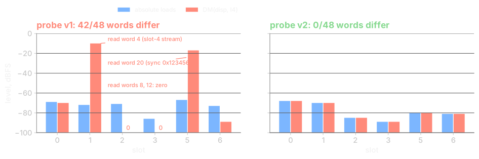
42 of the 48 words were different. The other 6 matched only because both sides were zero. “Zero misses” meant the pass completed, not that the words were right.
The wrong values gave the cause away. In frame 0 the indexed copy of slot s held ring word 4*s: slot 1 got the slot-4 stream, slot 5 got the 0x123456 sync word, slots 2 and 3 got the zeros at words 8 and 12. Every displacement was four times too large.
SHARC+ address arithmetic, as measured at this patch point
  DM(disp, I4)     effective byte address = I4 + 4*disp     (disp counts WORDS)
  MODIFY(I4, imm)  I4 += imm                                 (imm counts BYTES)
The hardware was doing what it should. My assembler and emulator treated both as bytes. Probe v2 emits word displacements for DM(disp, I4) and leaves MODIFY in bytes. On DSP4, at the same patch point, it matched the absolute copy in all 48 words.
| stage | what it was | result |
|---|---|---|
| probe v1 | indexed copy against absolute copy, same pass | 42/48 words different; frame 0 slot s read word 4*s |
| emulator fix | DM(disp, I4) displacement in words, MODIFY in bytes | host-tested |
| probe v2 | same comparison, array B DSP4 | 0/48 wrong; per-slot levels identical (0:-68 1:-70 2:-85 3:-89 5:-80 6:-81); sync 24/24; clean unpatch |
| levels hook | ran on DSP4 on 2026-11-16 with the byte assumption | its per-slot peaks are invalid; the corrected caller is merged and host-tested, not yet loaded on a board |
Where this leaves the array
I can copy a frame of DSP4’s receive ring with alignment checked by the sync words, and the indexed copy now matches the absolute one word for word. The noise floor in slots 0 to 3, 5 and 6 is real, but the register readout says the SPORT only captures slot 0, and I have not reconciled the two. What leaves the tile on the eight Dante channels is Part 7.